 EN
EN


Mechanical excavator inspection standards and methods! Industrial inspection standards!
Mechanical excavator inspection standards and methods! Industrial inspection standards!
The safety of mechanical excavators relates to technical measures in earthworks to eliminate or reduce risks arising from significant hazards, hazardous states or hazardous events in use, operation and maintenance. What are the inspection standards for mechanical excavators? How are mechanical excavators tested?
Mechanical excavators
A mechanical excavator refers to an excavator operated by a wire rope on the upper structure, which mainly uses a shovel, a bulldozer or a claw to carry out excavation operations; Use galvanized boards to solidify materials; Use hooks or balls for crushing operations; Also carrying materials using specialized working appliances and accessories.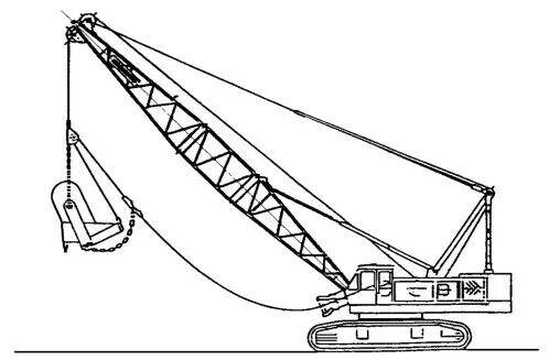
A portable mechanical excavator with shoveling equipment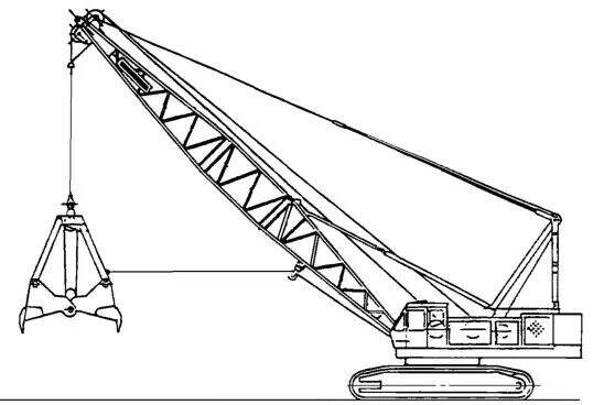
A portable mechanical excavator with a catcher equipment
Mechanical excavator inspection standard requirements
01
Mechanical excavator inspection - driver operating position inspection
- Mechanical equipment
The driver position of a passenger machine should be fitted with a driver's room.
Machines with a working mass greater than 1,500 kg and a driver's seat shall be able to be equipped with a cab. Machines with a working mass less than or equal to 1,500 kg are not required to be equipped with a driver's cab.
The design of earth machinery should ensure that adequate protection is installed when it is used in applications where there is a risk of debris splattering, such as the use of hydraulics.
- Minimal Movement Space
The minimum movement space of the driver shall comply with ISO 3411.
The minimum space in the driver's position and the position of the control device shall comply with ISO 6682
- Motion parts
Measures should be taken to avoid accidental contact with moving parts (e.g. wheels, belts or working or attached devices) from the driver's position.
- Engine exhaust
The exhaust gases emitted by the engine should be kept away from the driver and the cabin vent position
- Procurement of driver's books
A space near the driver's position for safe storage of driver's manuals or other instruction manuals should be provided, and if the driver''s position cannot be locked or if there is no driver's room, the space should be locked.
- sharp edge
There should be no exposed sharp edges or corners in the driver's working space at the driver''s position (e.g. the ceiling, internal instrument panels and access to the driver'"s position).
- Driver Location Climate Conditions
The driver's room should protect the driver from foreseeable adverse weather. The preparations for a ventilation system, adjustable heating system and a glass frost removal system shall be installed as required.
- Vessels and hoses
The driver's room is equipped with a fluid pressure greater than 5 MPa or a temperature greater than 60 C.
-Basic entrance and exit points
A basic out population shall be provided and its dimensions shall conform to the requirements of ISO 2867.
- alternate entrance and exit
A backup access point should be provided on a different side from the base population. Its dimensions should comply with the requirements of ISO 2867. One window or another door can be used to open or move without a key or tool. If the entrance can be opened from inside without the need for a key or tool, a plug can be used. Broken glass doors and windows of suitable dimensions may also be considered suitable spare population, provided that the necessary escape hammer is provided within the driver's room and is within reach of the driver.
- Air conditioning system
The ventilation system shall provide fresh air to the cab at a flow of not less than 43 m / h. The filter shall be tested according to SO10263-2.
- Frost removal system
The defrosting system should provide for a defrosting device for front and back windows, such as through the heating system or dedicated defrosting devices.
- Booster system
If a cab with a booster system is provided, the booster system shall be tested in accordance with SO 10263-3 and shall provide a relative indoor pressure of not less than 50pa.
- Doors and windows
Doors, windows and moving panels should be firmly bound to their intended working position. Doors shall be maintained in their intended working position through rigid restraints, and basic entrances and exits shall have been designed to be safely opened, and the restraint shall be readily loosened from the driver position or the driver population platform.
Car windows should be fitted with safety or other materials with the same safety properties.
The front window should be fitted with an electric wiper and cleaner.
The water tank of the window cleaner should be easily accessible.
- Interior lighting
A fixed internal lighting device shall be installed in the driver's room, which shall still function after the engine is turned off so that the driver''s position can be illuminated and the driver'll's manual can be read.
- Driver's protective gear
Mechanical excavators should be able to install protective structures for the driver (top protective gear and front protective gear). Manufacturers should provide protective structures (top protective devices and front protective devices) and the user should choose them based on the application risks present.
Falling Object Protection Structure (FOPS)
With the exception of the provisions of ISO 3449, machines intended for use in situations where there is a risk of falling objects shall be designed to be fitted with a falling object protection structure (FOPS).
02
Mechanical excavator inspection - driver controls and indicators
- Start and stop the device
Earth-moving machinery shall be equipped with starting and stopping devices (such as keys), the starting system shall have protective devices specified in SO10264 to prevent unauthorized use.
Surface machinery shall be designed so that when the engine is started or stopped, the machine, working units and accessories are not able to move without the starting controls.
—Unanticipated action
Manipulation devices that may cause hazards as a result of accidental operation shall be arranged or disabled or protected according to the principle of minimizing risk, especially when the driver enters or exits the driver position. The devices that disable the manipulation shall be self-activated or activated by forced stimulation of the relevant device.
-Pedal, pedal
They should be of suitable size, shape and sufficient distance between them. Steps should have a slippery surface and be easy to clean. Where the pedals of a earthen machinery and those of a car have the same functions (clutching, braking and acceleration), the pedals should be arranged in the same way to avoid hazards caused by confusion.
- Ancillary device made an emergency landing
If the engine is stalled, it should be able to:
· The working unit / accessories fall to the ground / mount;
· From the position where the driver activates the descent control device, the working / attached device can be seen to descend:
· Remove any residual pressure in each hydraulic and pneumatic circuit of the working / auxiliary device that may cause the risk.Measures for landing ancillary devices and devices for removing residual pressure may be placed outside the driver's position and should be explained in the driver''s manual
- Out of control sports
As a result of sliding or slowing (e.g. caused by leakage) or when the power supply is interrupted, except when the driver controls the operation, the movement of machines and working devices or accessories from fixed positions shall be controlled to the extent that they do not pose a risk to exposed populations.
- Visual displays / control dashboards, indicators and symbols
· The driver should be able to see from the driver's position the necessary instructions for the normal functioning of the machine, whether day or night.The glare should be minimized.
· Control indicators for normal operation and safety of machines shall comply with the provisions of ISO 6011 for safety and related matters.
· Symbols for visual display / control devices used in earth-moving machinery, if applicable, in accordance with ISO 6405-1 or S 6405-2.
- Measures to minimize the likelihood of being lifted from the ground as a steering device for a ride-type machine which is not expected to operate from the ground should be provided.
- Non-passenger machinery shall be equipped with a grip-operated device that stops the operation of the machine and the dangerous movement of the gear when the driver removes control. The design of the control device should take into account the risks arising from the accidental movement of the machine towards the operator.
03
Mechanical excavator inspection - steering system inspection
- The steering system shall ensure that steering manoeuvres are in accordance with the expected steering direction specified in ISO 10968.
- Belt machines The steering system of belt machines with forward / backward speeds exceeding 20 km / h shall be gentle.
04
Mechanical excavator inspection - reverse brake system inspection
Mechanical excavators should be equipped with a revolving operation and a stop braking system.
05
Mechanical excavator inspection - lifting system inspection
- Compulsory control (up / down)
The lift system of a mechanical excavator shall be equipped with brakes, which shall be initiated immediately after the handle or pedal is loosed. The braking system shall be automatically initiated in the event of loss of power or a decline in forced control. It shall not affect the stability of excavator operations and the braking system shall be capable of maintaining the rated load specified in 4.8
-Free drop operation
The lift system of a mechanical excavator shall be equipped with brakes and be activated immediately if: - the corresponding operation of the pedals;
Remove the manual steering lever.
The brakes shall be designed to provide continuous braking of the load in motion. The conductor should be designed to prevent the wire rope from rising or falling out of control
- Switch
During the switch from a mandatory control operation to a free-fall operation, there should be no situation where the load falls.
- Move your arms
The arms of a mechanical excavator should be protected from being re-inflated in the event of sudden unloading The arms should be equipped with a limit switch to avoid reverse overloading.
The joints (bolts) of the parts of the arm should be designed to be installed and dismantled without a person standing under the arm.
- wire rope
The safety factor for mechanical excavator wire ropes should be determined according to the table below.
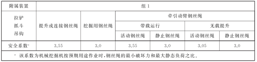
Safety factor for wire rope
- wire rope tubes and wire rope pulley
· Wire rope cartridges and wire rope pulleys should be designed and constructed to avoid wire rope damage and wire loosening or distraction.
· The ratio between the diameter of the wire rope coil and the diameter thereof shall be at least 20: 1.
· Wire pulley The ratio of wire pulley diameter to wire diameter measured at the trough should be at least 22: 21.A ladder for shoveling a wire rope, except a guide pulley and an auxiliary wire rope.
· The rim of the winch wheel and the edge of the wringing cylinder should be at least 1.5 times the diameter of the wire rope.
06
Mechanical excavator inspection - Restriction device inspection
- Load torque limiter
In material handling conditions, lift systems and arm lifting systems shall be equipped with a load torque limiter to avoid overloading, which shall be set to the rated load specified in 4.8 with a tolerance of 100%. After the load torque limiter is operational, it should be able to reduce the load threshold 4.7.2 Increase the limit switch.
In material handling conditions, mechanical excavators should be equipped with a limit switch for raising motion. After the positioning switch is activated, the arm should be able to fall.
- Limit switches for the arm lift system
The arm lift system of a mechanical excavator should be equipped with a limit switch to avoid reverse overloading of the arm. After the range switch is in operation, the arm should be able to fall.
07
Mechanical excavator inspection - stability inspection
- Under maintenance, assembly, dismantling and transport operation conditions specified by the manufacturer in the driver's manual, earthen machinery designed and manufactured with working and auxiliary devices, including optional devices, shall provide adequate stability. Devices used to increase the stability of earthmoving machinery in operation mode should be fitted with a interlocking device or a one-way valve to secure the hose in case it fails or is full.
- Tow the shovel, the operational capacity of a mechanical excavator in tow conditions shall be the lesser of the following:
A) 75% of the calculated tipping load P;
B) Maximum lifting capacity of winch.
The capacity specification of the shovel shovel should be determined by the manufacturer
- Gripping and shoveling
The operational capacity of a mechanical excavator in a clawing and shoveling condition shall be the lesser of the following:
· 66% of the calculated tipping load P;
· Maximum lifting capacity of the winch.
The capacity calibration of the shovel shall be determined according to ISO 7546, and the capacity calibration of the grab shall be determined by the manufacturer.
Shanghai hangkui Construction Machinery co., Ltd , always with professional , accurate , fast and enthusiastic comprehensive quality assurance service to escort customers to win the market .Inspection business all over the world, based on the regional professional inspectors, to provide a range of quality management and consulting services。Shanghai hangkui Construction Machinery co., Ltd can provide you with product inspection, supplier audit, quality management consulting and other services, to provide a series of professional quality technical support for your trade.
Tel: 15736904264
Official website: www.cnhangkui.com
Email: [email protected]

 ONLINE